You are here:
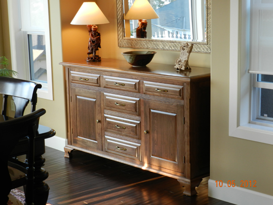
Design and Construction of a Sideboard with Ogee Feet
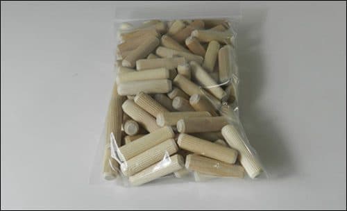
Sideboard project has 95% dowel construction.
ALWAYS THINK SAFETY! Drill bits can shatter during use. Always wear safety glasses when operating power tools. Always disconnect power before changing drill bits.
Table Saw: 1/ Maintain concentration! 2/ Use a Riving Blade 3/ Use push sticks or feather boards 4/ Never place hands behind blade 5/ Wear goggles
Router or radial arm saw: Always read and follow all manufacturers safety guidelines.
For inquiries on furniture design and dowel construction please call Toll Free
1-877-986-9400
Create design sketch of sideboard with ogee feet.
P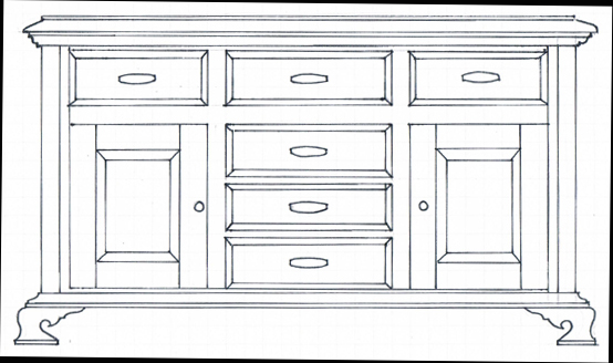
Prepare work piece for Ogee shape feet – Block 1-1/4″ x 4″ x 15″ with 45 degree mitered ends – 4 of. Each 15 inch work piece incorporates 2 Ogee feet. Use a test piece to ensure the 45 degree and 90 degree cuts are accurate.
For reasons of simplicity and aesthetics, I have since changed the design. In other words the side profiled component of the Ogee foot is extended back to the rear of the sideboard, omitting 2 complicated profiles.
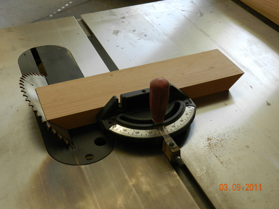
Cutting 45 degree angles on ogee feet
Prior to cutting, check settings on both table saw and mitre gauge, and use test pieces.
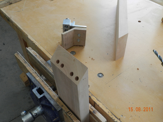
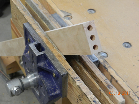
Once the 2 mitres are cut on one work piece, drill the dowel bores as required. Drill these as close to the inner corner as possible to avoid breaking through at the outer profile.
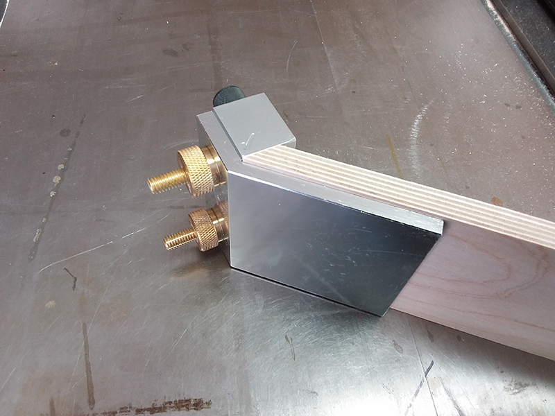
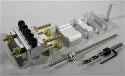
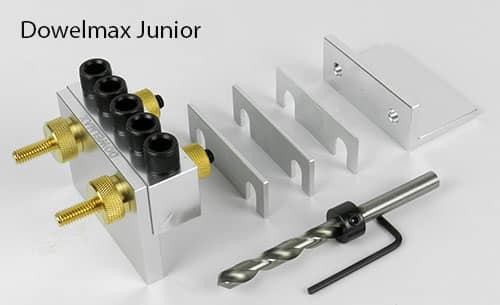
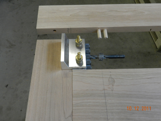
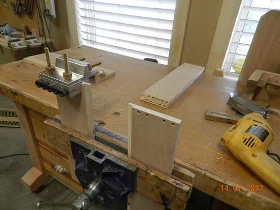
New Dowelmax accessory for 45 degree angles
Use Dowelmax mitre accessory to drill 4 bores. Use suitable spacer to position bores close to the inner corner.
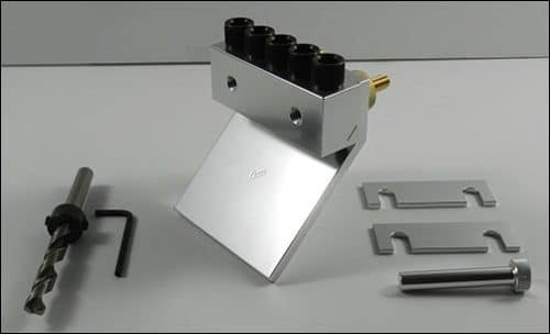
Position and align Dowelmax miter joint configuration with the new 45 degree angle accessory to drill 4 accurately placed dowel holes.
Dowels are positioned away from the outer edge by use of the 3/8 spacer.
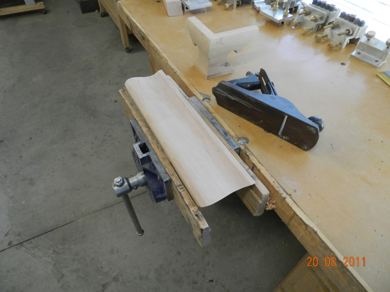
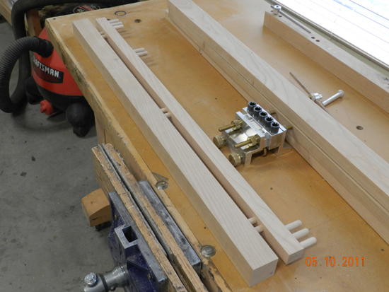
The concave section of the Ogee feet is shaped on the table saw. A long fence is positioned and clamped to the table top at approx. angle of 45 degrees.
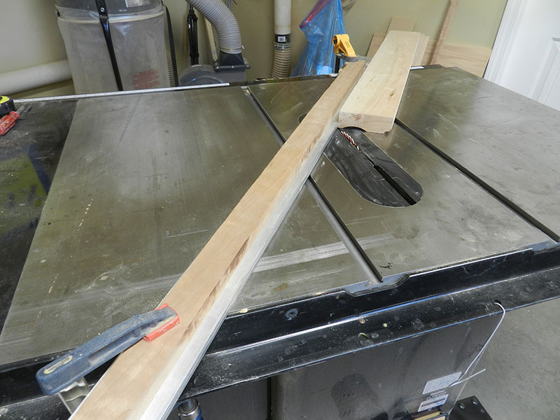
Concave profile milled by table saw into work piece used to build the armoire ogee feet.
NOTE: operator’s position is on the far side, as shown in above photo
NOTE: The fence must be positioned between the blade and the operator to ensure that the horizontal load imparted to the work piece by blade rotation is countered by the fence. Implement 2 or 3 passes, adjusting blade height until the desired curvature and depth is attained (approx. 1/4 to 3/8 inch). Adjust distance between blade and fence to provide a 1/2 inch shoulder at lower edge. Shape the top section with a small plane, spoke shave or router. Use 1/4 inch. hardboard template to provide line sketch of end profile. Cut profile on bandsaw.
Use spoke shave or small hand plane to shape curvature
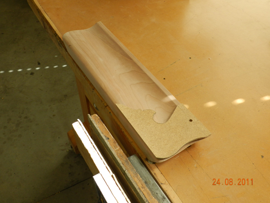
Mark inner curvature of ogee feet using template and shape in the bandsaw.
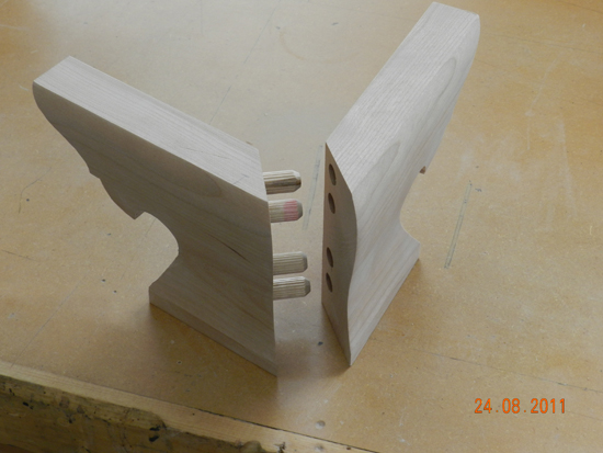
Glue and clamp feet.
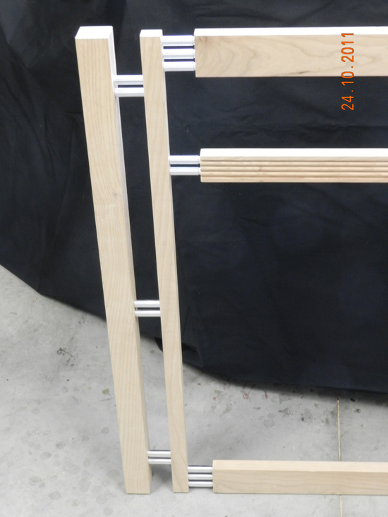
Prepare four corner posts: 1-5/8″ x 1-5/8″ x 31-1/8″.
The two front posts have mating inner verticals: 1″ x 1″ x 31-1/8″. The inner vertical has a relief or offset of 1/4″ from the face of the front post. The dowel placement is staggered to avoid fouling. Ensure all posts and inner verticals are identical in length in order to reference from both the top and the bottom. Use distance gauge to drill drawer support rail bores and extended distance gauge for centre join on inner vertical.
Top rail with 3 dowels
CONSTRUCTION OF FRONT AND REAR RAILS
Prepare front and rear rails. Front rails: Two of 7/8″ x 2-/18 x 55″ and one of 7/8″ x 1-1/2″ x 55″. Rear rails: Two of 7/8″ x 2-1/8″ x 57″ and one of 7/8″ x 1-1/2 x 57″. Ensure all lengths are identical and all ends are square.
Reference from the top three equidistant dowels in 2-1/8″ rail and two equidistant dowels in 1-1/2″ rail.
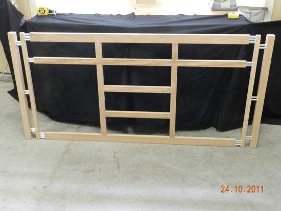
As a consequence of our Dowelmax slide design, it is necessary to mirror the rear rail assembly identical to the front.
Prepare front and rear inner verticals for drawer assembly: Four of 7/8″ x 1-1/2″ x 27″. Prepare horizontal drawer rails: Two of 7/8″ x 1-1/2″ x 18″. Drawer face heights : Three along top – 4-1/4″; Three at lower center – 6″.
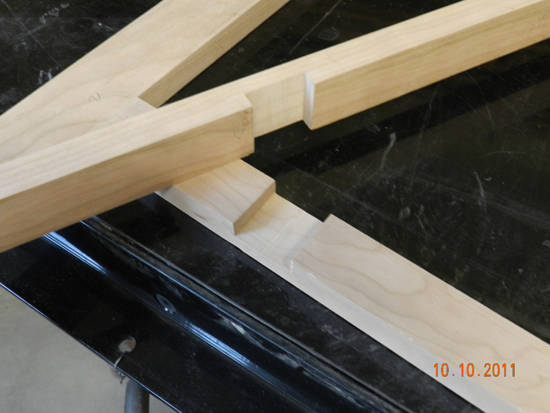
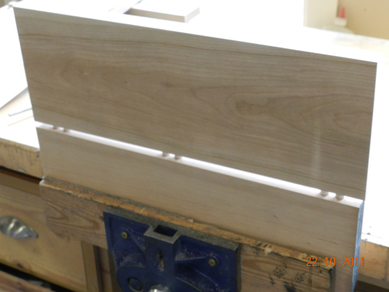
LAP JOINTS ON SIDEBOARD INNER VERTICALS CREATED WITH DADO BLADE ON THE TABLE SAW
In order to maintain continuity of the inner verticals (2), it was decided to create half lap joints at the juncture of the second from top drawer rail and the 2 mid verticals (see following photograph)
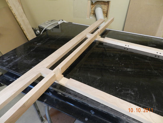
The half lap joints where the inner verticals meet the intermediate rail.
RAISED PANEL COMPONENTS
The raised panel system is used at both ends of the structure and also for design of the 2 front doors. The side panels form part of the strutural integrity and should be reinforced.
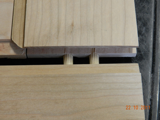
Raised panel reinforced with dowels at all 4 corners
The raised panel system is visually pleasing however in this case, end panels form part of the overall structural strength, and so in my opinion, must be reinforced.
Route rails, stiles and panels for transverse end panels. Stub tenon is 3/8 penetration and requires additional strength. Use shop made stop arrangement to cut stiles to identical lengths and then reference Dowelmax from the top and the bottom to install two dowels at each corner. A spacer is required to center on the stub tenon and collar depths are required to be adjusted to accomodate the tenon length and mortise depth.
Work piece sizes for two end panels:
Stile: 4 of 7/8″ x 3-1/4″ x 31-1/8″
Rail: 4 of 7/8″ x 3-1/4″ x 9″
Panel: 2 of 7/8″ x 9″ x 25-1/4″
Finished Assembly: 14-3/4″ x 31-1/8″
Center panel is 9″ wide so 2 – 4-1/2″ panels are joined at center line using 6 dowels and the distance gauge.
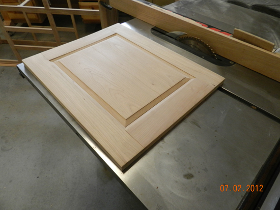
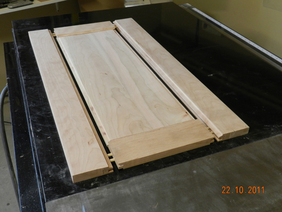
DESIGN FOR RAISED PANEL DOOR
Route door rails, stiles and center panels identical as for end panels. Again use 2 – 1/4 ” dowels in each corner, and 6 – 3/8 dowels to join the two center panel work pieces to widen the center panel as shown above. Each door consists of:
Stiles: 7/8″ x 3″ x 21″
Rails: 7/8″ x 3″ x 11-3/4″
Panel: 7/8″ x 11-3/4″ x 15-3/4″
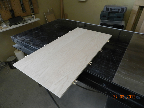
CONSTRUCTION OF SIDEBOARD TOP
The top can be constructed with straight boards and 3 boundary mitred rails, however since the sideboard top is readily visible, I like to vary the design to include sections with the grain running in opposing directions. (see following photo)
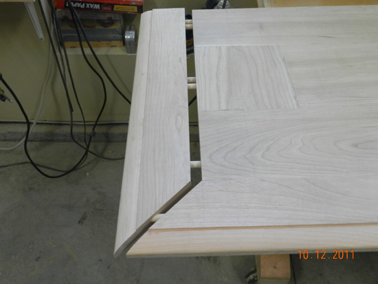
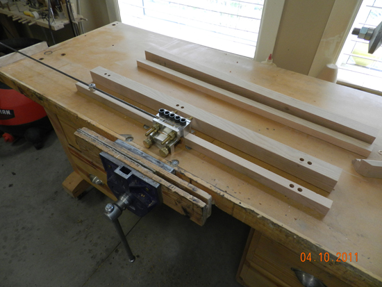
The photo above shows dowel placement for the mitred boundary rails all on the same axis.
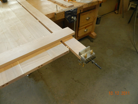
Position of Dowelmax on long rail (before mitre) to ensure dowel placement on the same axis
Above photo shows position of Dowelmax to align bores on end mitre rail (all dowels in same axis)
CONSTRUCTION OF SIDEBOARD DRAWER
Normally I prefer solid cherry milled to 5/8 inch thick for drawer construction, however on this occasion I chose to use 1/2 inch Baltic Birch plywood, an excellent product.
Drawers: Cut front, rear and side panels for all six drawers using baltic birch or oak faced plywood.
Top Centre Drawer(One): 1/2″ x 4-1/8″ x 17″ – 2 of, and 1/2″ x 4-1/8″ x 14-1/2″ – 2 of;
Left and Right Top Drawers(Two) : 1/2″ x 4-1/8″ x 16″ – 2 of, and 1/2 x 4-1/8″ x 14-1/2″ – 2 of;
Lower Mid Drawers(Three) 1/2″ x 5-3/4″ x 17″ – 2 of and 1/2″ x 5-3/4″ x 14-1/2″ – 2 of.
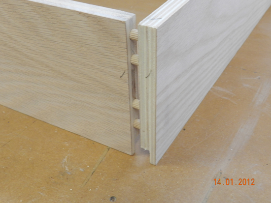
Butt join drawer front and rear to inside of drawers sides so that no raw edge is visible when drawers are open. Rabbet lower insides of panels to accept drawer bottom to el
Use Dowelmax 1/8 spacer fastened to reference bracket by supplied capscrews to center 1/4 inch dowels on 1/2″ plywood. Use 4 x 1/4″ dowels on smaller drawers. When using 1-1/2″ long dowels, adjust drill collar to drill bores 1-1/8″ deep to compensate for shorter bores on face joint for drawer sides.
Position of Dowelmax at ends of front and rear drawer walls for hole placement (larger drawer – 5 dowels)
Use 5 x 1/4 inch dowels on larger drawer using supplied index pin to extend the dowels along the end of the drawer fronts. When using 1-1/2″ long dowels, adjust drill collar to drill bores 1-1/8″ deep to compensate for shorter bores on face joint for drawer sides.
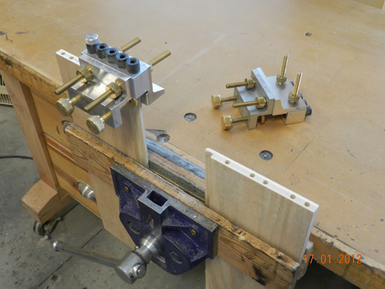
Change the Dowelmax to the second configuration to drill dowel bores into the drawer side faces. For face joint, adjust collar stop to shorten drilling depth to 3/8″ deep to avoid drilling through drawer side.
Placement of 5 dowels on deeper drawer using 1/4 inch indexing pin and with Dowlelmax in the second configuration
With Dowelmax in the second configuration, use 5 x 1/4 inch dowels on larger drawer using supplied index pin to extend the dowels along the end of the drawer fronts. For face joint, adjust collar stop to shorten drilling depth to 3/8″ deep to avoid drilling through drawer side.
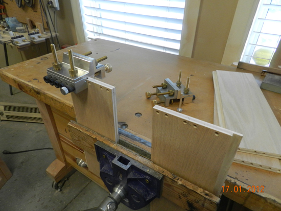
Dowelmax in face configuration for smaller drawer (4 dowels)
Bulkhead/Partition: 15-3/4″ x 31-1/8″ segregating drawer space from cupboard space and to provide additional strength and rigidity. Eight double dowels each end on two bulkheads (use distance gauge set at approximately 7-1/2″) Reference from top, affix to two inner verticals on front and rear framework. Use 1/2 inch oak faced plywood and 1/4″ dowels.
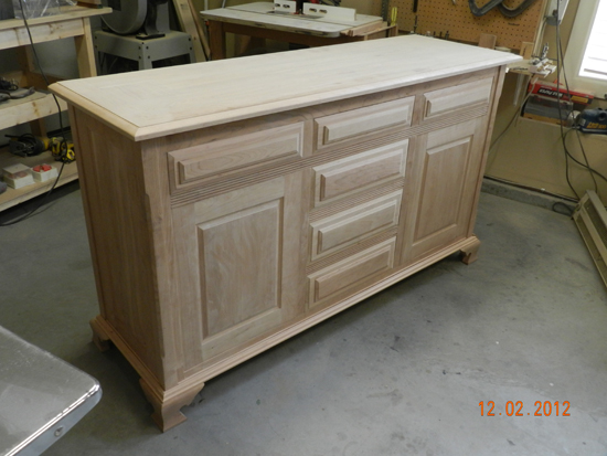
Sideboard ready for final sanding.
To facilitate final finishing, disassemble alll sections and lay out flat. Cover dowel holes and surfaces to be glued with painters tape. Place the tape carefully so that when the various components are joined, no bare unstained surfaces are visible. For cherry I use a conditioner made up from shellac and methyl hydrate , 1 part shellac to 3 parts methyl hydrate. Apply conditioner liberally with the grain, rub in and leave overnight.
Again, the stain is easier to apply with the various pieces flat and no protruding surfaces to cope with. Apply dark walnut stain with the grain. Allow to settle and be absorbed by the surface pores, then rub in, removing the excess at the same time. Re-do after 24 hours if a deeper slightly darker coat is needed.
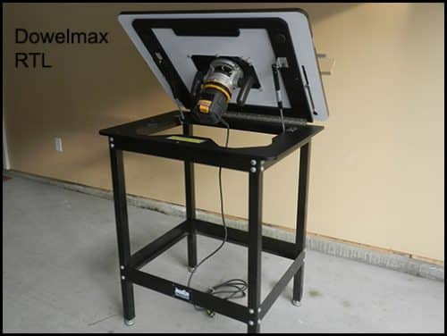
I use a Turbo-Air system together with a water based lacquer for the final coats. I built a vertical stand with casters to enable me to rotate the piece during the spraying process. I would suggest at least three coats to finalize.
Assembly: I use a small stiff artists paint brush to apply the glue, coating the inner periphery of the holes, the exterior of the dowels, and the mating surfaces. Try to avoid excess coating, however if excess seeps out it is much easier to clean off finished surfaces than bare wood.